Curtis.Castiglione@ROzebra.com

Master Cylinder Design: Tandem Circuits and Secondary Actuation
Tandem Circuit Architecture and Redundancy Logic
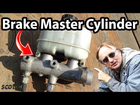
The tandem master cylinder is the primary pressure generation component in split-circuit hydraulic systems. It incorporates two independent pressure chambers—primary and secondary—within a single bore to provide fail-safe redundancy. During nominal operation, the primary piston is displaced by the input rod, creating hydraulic pressure that acts as a fluid link to actuate the secondary piston.

Redundancy is maintained through specific mechanical fail-safes for different failure modes:
- Primary Circuit Failure: If the primary circuit loses integrity, such as a ruptured line, the primary piston travels forward until it makes physical contact with the secondary piston. This establishes a direct mechanical link to actuate the remaining functional circuit.
- Secondary Circuit Failure: If the secondary circuit fails, the primary piston generates pressure against the secondary piston. Lacking counter-pressure, the secondary piston travels until it hits the cylinder end-stop, allowing the primary circuit to build and maintain pressure.
Modern passenger vehicles typically utilize a diagonal split (X-split) configuration. This layout ensures that a single-circuit failure retains 50 percent braking force and maintains directional stability by controlling one front wheel and the opposite rear wheel.
Seal Dynamics and Internal Porting Mechanisms
The master cylinder utilizes precision elastomer seals (cups) to isolate hydraulic pressure and facilitate fluid movement throughout the stroke.
Seal Configuration
The primary cup of each piston generates hydraulic force. Its flared design causes it to expand against the cylinder wall as pressure increases, ensuring a high-pressure seal. The secondary seal, located at the rear of the piston assembly, isolates the circuits from each other and prevents fluid from leaking past the piston into the brake booster or out of the rear of the housing.
Fluid Replenishment
Traditional master cylinders utilize a compensating port and a supply port. When the brake pedal is released, the piston retracts past the compensating port, allowing fluid to move from the reservoir into the pressure chamber. This accounts for thermal expansion or fluid displacement caused by brake pad wear.
In vehicles equipped with Advanced Braking Systems (ABS) and Electronic Stability Control (ESC), center-valve designs are frequently implemented. A spring-loaded valve located within the piston opens when fully retracted, providing a high-flow path for fluid replenishment. This is critical for the rapid pressure modulations required by modern electronic safety systems.
Advanced Integration: Brake-by-Wire and Regenerative Blending
Modern Electro-Mechanical Power Brake (eBKV) and Brake-by-Wire (BbW) systems often decouple the physical connection between the pedal and the master cylinder during normal operation.
- Pedal Feel Simulators: These provide tactile feedback to the driver while a sensor detects pedal travel and force. The electronic actuator then drives the master cylinder pistons independently.
- Regenerative Blending: In hybrid and electric vehicles, the system may delay hydraulic pressure application, using the master cylinder only as a backup while electric motors provide braking torque for energy recovery.
- Fail-Silent Mode: If a fault is detected in the electronic control unit, a bypass valve closes to re-establish a direct hydraulic link between the driver and the tandem circuits, ensuring manual override capability.
Diagnostic Protocols for Internal Hydraulic Failure
Internal failures can occur without external fluid loss, requiring specific procedures to identify seal bypass or porting malfunctions.

- Static Pressure Drift Test: Apply constant, moderate pressure to the brake pedal for 60 seconds. A gradual sinking of the pedal to the floor without external leaks indicates an internal bypass where fluid is slipping past the primary piston cup into the low-pressure side of the circuit.
- Pressure Differential Analysis: Connect twin hydraulic gauges to the primary and secondary output ports. Apply the brakes and monitor the pressure rise; a significant deviation between the two circuits indicates compromised internal seal integrity or a blockage in the internal porting.
- Port Functionality and Reservoir Observation: Monitor the reservoir fluid level while slowly depressing the pedal. In port-and-orifice designs, a minor squirt of fluid back into the reservoir at the start of the stroke is normal. Excessive turbulence or a lack of pressure buildup suggests the primary cup is failing to seal past the compensating port or the center valve is stuck in the open position.
Written by Curtis Castiglione



No Comments Yet
Be the first to comment on this article.