Curtis.Castiglione@ROzebra.com

Ford Electrical Diagnostic Efficiency
Course Title: Efficiency in Ford Electrical Systems
- Isolate circuit failures across power, ground, and communication networks.
- Validate scan tool data using physical circuit measurements.
- Justify diagnostic labor hours by preventing unnecessary parts replacement.
PRECISION ELECTRICAL FAULT ISOLATION

Modern repair centers on diagnosis. Replacing parts without testing is guesswork. A failed sensor often masks underlying wiring faults. Technicians must verify the entire circuit path. This includes power supply, ground integrity, and network signals. Modern Ford vehicles utilize complex multiplexing. One module failure can disrupt the entire CAN bus. Symptoms are often identical across different failure points.
Relying solely on Diagnostic Trouble Codes (DTCs) leads to misdiagnosis. A code indicates a circuit state, not a specific failed component. Technicians use VIN-specific wiring diagrams to map test points. Measuring voltage drop and resistance pinpoints the exact break. This process takes time but prevents replacing functional parts. Replacing three modules to fix a broken ground is inefficient and costly. Professional diagnosis ensures a fix-it-right-the-first-time result. It justifies labor hours by eliminating guesswork and returning the vehicle to service faster. Accurate testing is the only way to navigate increasingly complex vehicle electronics.
- Perform a full system scan to identify active and stored DTCs.
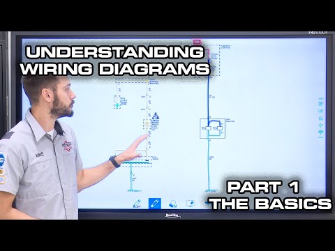
- Access the Ford wiring diagram for the specific VIN and build date.
- Test for battery voltage and ground integrity at the component connector.
- Use an oscilloscope or multimeter to verify signal communication.
- Inspect physical connectors for corrosion or terminal tension issues.

Pro-Tip: Never trust a DTC alone; always verify circuit path integrity before condemning any electronic control module.



No Comments Yet
Be the first to comment on this article.