Curtis.Castiglione@ROzebra.com
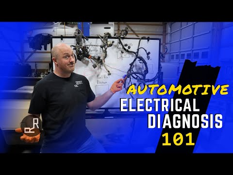
Automotive Module and Wiring Diagnostics
Course Title: Advanced Module Diagnostics and Harness Integrity
Learning Outcomes
- Distinguish between module hardware failure and wiring-induced symptoms.
- Execute critical power and ground verification under electrical load.
- Detect signal corruption caused by environmental harness damage.
Diagnostic Protocol for Module Replacement
Control modules depend entirely on electrical signal integrity. Harsh environments—heat, vibration, and road salt—degrade wiring long before hardware typically fails. When a module stops communicating or triggers U-codes, the wiring is the primary suspect. A damaged circuit mimics total hardware failure by starving the unit of power, ground, or data. Follow these verification steps before condemning any component:
- Measure source voltage at the module connector while the circuit is under load.
- Perform a voltage drop test on the ground side to ensure a low-resistance return path.
- Inspect connectors for moisture intrusion, backed-out pins, or fretting corrosion.
- Test communication bus resistance and check for shorts to power or ground.
- Locate harness rub-through points near moving engine components or exhaust heat.

A module requires three things to function: stable power, a clean ground, and a valid communication path. If any variable is compromised, the module will appear dead. Replacing the unit without fixing the underlying harness issue results in an expensive, unnecessary comeback. Always verify the circuit environment before replacing the hardware.

PRO-TIP: Use a test light to load-test circuits; multimeters often show ghost voltage through a single intact wire strand.



No Comments Yet
Be the first to comment on this article.